Posts

Showing posts from February, 2013

CIPT1 Notes

CUCM Basic Information: CUCM Began with Windows NT and a Windows structured environment, then progressed to Linux. In 3.X release of Call Manager Cisco made it so that Call Manager had to be installed only on Cisco MCS Servers. Previously it could be installed on anything. VMWare is allowed specifically for virtualization of UC. Not a Hyper-V (Yet) Call Manager is the same thing as Cisco Unified Communications Manager Run time Data ( Intra Cluster Communication) Actively runs between CUCM servers Ex. Phone registration Ex. Cucm failure results in phone reallocation Database Data ( Database Replication ) Cucm Database Information replicated between servers Ex. Phone extension mapping Ex. Dial Plan changes  CUCM Functions Call processing Signaling and device control Dial Plan administration Phone features CUCM Manager Signaling and Media Paths SCCP SIP RTP - Realtime transfer protocol ( does not go through CUCM)

Call Manager Database Replication Check (3 Ways)

Image
After going through my lab I added a Call Manager Publisher / Subscriber cluster. Going through the setup I was going to check the database replication status. Here is the awesome command to use in the CLI. Check database replication method 1: show perf query class "Number of Replicates Created and State of Replication" What comes up is a replication status of "2". This is definitely what we want to see. 2 = GOOD! When checking the database via CLI make sure you do it on both servers/all servers in the  cluster. Check database replication method 2: Another way to do it is to generate a report inside of CUCM.  When checking a report in CUCM. Go to the Cisco Unified Reporting Page and when you login select the "System Reports" tab on the top left. Once you select that tab make sure you go down to Unified CM Database Replication Status and Generate New Report.  Check database replication method 3: A third way to check the database re

VPN 3000

Image
How to retrieve group passwords from a VPN 3000 ! 1- Go to Administration  ...then...  Access Rights  ....then Access Settings  and   select "None" under "Config File Encryption". 2. Go to Administration ... then..   File Management. .then   XML Export and select a name  for the XML file. The name of the file can be something as simple as "test",  "vpnconfig", or whatever you deem necessary for your configuration file. This will export your VPN configuration file into a XML  file. This file can then be retrieved in File Management. 3.Click the main category of File Management ...then find the configuration in the list and click "view" . To see the un-encrypted configuration. *** Hint : Remember to change the configuration back to RC4 encryption. Apply and save.

ASA RAM Requirements for IOS Upgrading

      While looking into NAT translation rules and upgrading here is a nice table from Cisco if you're looking at upgrading anytime and need some RAM requirements like I did.   Cisco ASA Model Minimum RAM Requirements (pre Cisco ASA 8.3) Minimum RAM Requirements (post Cisco ASA 8.3) Default Shipping RAM on New Cisco ASA Adaptive Security Appliances (as of Feb. 2010) 5505 10-User 256 MB 256 MB 512 MB 5505 50-User 256 MB 256 MB 512 MB 5505 Unlimited-User 256 MB 512 MB 512 MB 5505 Security Plus 256 MB 512 MB 512 MB 5510 256 MB 1 GB 1 GB 5510 Security Plus 256 MB 1 GB 1 GB 5520 512 MB 2 GB 2 GB 5540 1 GB 2 GB 2 GB 5550 4 GB 4 GB 4 GB 5580-20 8 GB 8 GB 8 GB 5580-40 12 GB 12 GB 12 GB

HSRP With DHCP

Image
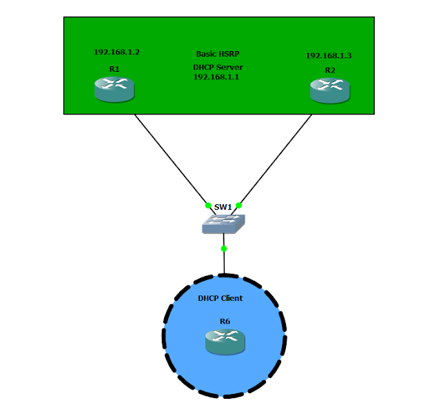
In this scenario below what we have configured is Hot Standby Routing Protocol ( HSRP) with DHCP HSRP is configured for redundancy so if one link goes down we have a transparent recovery and that pretty is much immediate. When we use a default gateway it will be the gateway of 192.168.1.1  ( This is the virtual IP address of both routers and the gateway for all end users. In this configuration we use a router for a "host" simulation and place the port on R6 to initiate a dhcp request. Configuration : DHCP POOL CONFIGURED ON BOTH R1 and R2 ip dhcp excluded-address 192.168.1.1 192.168.1.5 ( Exclude the IP's that we do not want allocated out ) ip dhcp pool DATA    network 192.168.1.0 255.255.255.0 (Define the network scope we want to give out )    default-router 192.168.1.1   ( The default router is the virtual IP that we setup for HSRP ) R1:  interface FastEthernet0/0  ip address 192.168.1.2 255.255.255.0  duplex auto  speed auto  standby 1 ip

(Terminal Length)Get rid of the show run more!

Image
Whenever we do a  "show running-configuration"  we always see a  " --More--". I know some people that might say this is just how it is so deal with it but it's not!!!!!  We can look at the whole running configuration and just use the scroll bar on the right hand side to see the whole configuration or better yet.... If we have a longer configuration that we need to look through we can print it out and read through it on a text document, wordpad, or whatever you use. Lets say you're doing some configuration check and for this instance we are using PuTTY. Inside PuTTY you want to create a log and have the entire running configuration without having a bunch of more statements like the following:: In this configuration print-out you can see the "more" lines being printed out when we typed in show running-configuration. We are going to change this with "terminal length 0" We type in terminal length 0 and we will r

Cisco Unity Give End User Administrator Access

Image
So working on another request that came through it was to allow administration access for a domain user to unity. Unity has class of service under subscribers that you can setup to allow the setup to either give administrative abilities or regular subscriber abilities. The image to the left shows the template of what the categories look like. We will have to go under the class of service tab.             NEXT ..... After going into the Class of Service Tab you will see some of this nature with a "Default Subscriber". Also we can create or see another class for administrative access.  For this purpose we will use the Default Administrator Templates: So go to the upper right hand and search so we can find the Default Administrator Account or create one.  We are now in the Default Administrator Account. In the account to the left under "Class of Service" we see System Access.  This is where we will see the Administrative Privileges to ass

DHCP with Basic EIGRP

Image
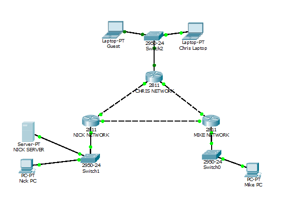
Throughout this lab are DHCP scopes defined on each network router. All scopes are a /24 subnet.  We separate the subnets with VLAN's. Each network is running the following vlan configuration: Configured on all switches:  vlan 10 name SERVERS vlan 20 name DATA vlan 30 name GAMING vlan 40 name GUEST interface FastEthernet0/1 (create a trunk from switch to router that carries over all vlan traffic)  switchport mode trunk interface fa0/X ( "X" represents the interface number that you will configure) switchport mode access ( make it an access port for the PC, laptop, server, etc) switchport access vlan X ( "X" represents the VLAN access you will give the device plugged into this port to allow it to request DHCP from the appropriate scope) The following is the EIGRP configuration for each network to talk back to the other networks: Nick Network router eigrp 24 network 1.1.1.0 0.0.0.15 network 192.168.1.0 0.0.7.255 no auto-summary

RIPV2 with Basic Authentication

Image
In the image above is a sample topology of three routers configured with RIPV2.  Some things to note : Loopback Interfaces:      The Loopback interfaces are representing our networks behind the router itself that faces the outside world. Key Chain      When making the key chain we will call it RIPV2 we can call it anything we want like NICKSKEY, spurs, or anything you can think of really.       **** Remember after creating the key we have to enable it on the interface that is advertising RIP traffic ! not inside the router rip configuration itself!  A good analogy of this is think of a cook in the kitchen when you're going to a restaurant. The cook has all the utensils and "networks" to get the job done and make the all the meals in his kitchen ( in our case keep the networks inside our RIP configuration) BUT who does the advertising or talking? Its the waitress or the interface talking to other networks! So the waitress or the "interface"  has to kno

FIPs Issue with Anyconnect

Image
So lets say you are getting the FIPs error that looks like : This is one annoying issue let me tell you. So I was installing a VPN client after establishing a new profile on for the Anyconnect Client. Well low and behold I get the FIPs issue.  Just to note the ASA does not give out any certs and had no certs on it so I had to make a change to the local machine.  The change is as follows : C:\ProgramData\Cisco\Cisco AnyConnect Secure Mobility Client In order to get to the directory make sure you have "Show hidden files, folders, or drives" selected in your folder options so you can see the Program Data Folder. Go to that directory and once in that directory we will have to change the file called: AnyConnectLocalPolicy.xml We have to change the following code to be "false" where it states "true" and then save the file as the same name and directory replacing the old. <?xml version="1.0" encoding="UTF-8"?>

Basic Ripv2

Image
This is a basic RIPv2 topology using GNS3. GNS3 is a great program if you get a chance to use it, I like all the functionality it has to it. So some facts/updates about RIPv2     Distance Vector Protocol      Routing updates sent via multicast at 224.0.0.9  as opposed to RIPv1 which uses broadcast     You must enable version 2 when configuring !  " version 2" ( You will see the configuration down the page) Administrative Distance of 120 So now that we have a couple updates on RIPv2 we are going to configure a basic RIP topology and when you're done you should be able to go to R1 and see the following " show ip route ":    1.0.0.0/32 is subnetted, 1 subnets C       1.1.1.1 is directly connected, Loopback0      2.0.0.0/32 is subnetted, 1 subnets R       2.2.2.2 [120/2] via 172.19.33.2, 00:00:20, FastEthernet0/0      3.0.0.0/32 is subnetted, 1 subnets R       3.3.3.3 [120/1] via 172.19.33.2, 00:00:20, FastEthernet0/0      172.19

Basic Static Routes

Image
In this LAB it is basic static routing that allows us have communication between all networks. This topology was built using packet tracer. What was put in was several different ways to do basic static routing either with one or two static routes. Also for ease of use all devices have the same following information:               enable secret cisco           line con 0               logging sync              password cisco              login           line vty 0 4               logging sync              password cisco              login Nick Router:                 Networks :                         192.168.20.0/26                         192.168.20.64/26                         172.16.20.0/24 ( We could really just make this a /30 but for simplicity it was a /24) Nick Router Configuration:        interface fa0/0        ip add 192.168.20.1 255.255.255.192        no shut        description Link to Switch        interface fa0/1        ip add 192.168.20.65 2